3D Models
Limited 3D models are available for download through our web site for some headers for PCB layout purposes. You are required to, at a minimum, provide your name and your company name and agree to our license terms. The file types offered are Iges, Step and Acrobat 3D.
If available, the models can be found listed by series from the following link: Alphabetical Search by Series
If the models are not listed, please contact your local sales rep and JST Regional Manager at the following link: JST Reps and Distributors
BHS Series
The difference is the width of the contact lance. The “A” style is the latest version with a lance that is about twice the width of the original contact (without the “A”).
The contact was modified and went into effect in April 2003 to improve contact retention within the housing and to help prevent accidental extraction and slippage of the contact from the housing.
As the contact lance has been modified, so has the applicable housing. The housing to be used with contact SBHS-002T-P0.5A is part number BHSR-02VS-1(N); the (N) indicates a modification of the housing lance to accommodate the contact with the modified lance.
For further details please contact us at the following link: Contact Us
Cage Code
Our current CAGE code is 67D17.
Our previous code (0S0L1) is obsolete and may still reference our old address location in Mount Prospect, IL.
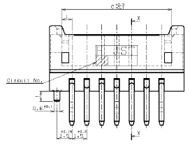
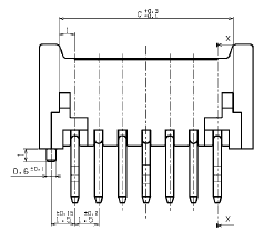
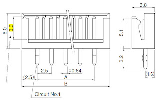
CZ Family
Enacted in January 2004, the (V) indicates a configuration change made to the top-entry headers to step-up flowability of the molding process and improve productivity and stability. The change does not affect performance of the connector. Below are schematics showing the revision.
ECCN
EH Series
The difference is the post length. Those with the “-A” suffix have a post extension length of 3.3mm (standard). Without the “-A” suffix, the post extension length is 4.0mm (normal length for the side-entry headers).
More information may be found on the datasheet at the following link: EH Series
FDZ Series
The FDZ series incorporates a sliding lock mechanism (slider) to lock the applicable FPC into the connector. Prior to the year 2000, the FDZ series was packaged and shipped with the slider in the open position.
Shipping in this method may cause the slider to break and / or damage the connector.
It was decided to package and ship the slider in the semi-locked position to help prevent breakage during packaging and shipping processes. To distinguish the new method from the old for first in, first out (FIFO) inventory control, an (S) was added to the suffix of the applicable parts.
Since 2000, only the parts with the incorporated (S) in the part number can be ordered. An example of the part number would be 13FDZ-BT (S)(LF)(SN).
The part is no longer provided with the slider in the open position from the factory [without the (S)].
FLZ Series
The difference is the material to conform to RoHS compliance.
The older SM1 / RSM1 are of 46 Nylon.
The compliant SM2 / RSM2 are of Glass-filled PA6T Nylon. These better withstand the higher temperatures required for the lead free solder reflow process.
General
The majority of JST through-hole type header wafer materials cannot withstand the temperatures required for reflow soldering (pin-n-paste). The through-hole headers are designed for wave or dip soldering methods.
Certain connectors are offered with gold plating depending on the series and / or the JST part number. Most are custom per customer / request. For details please contact your sales representative at the following link: JST Reps and Distributors
The following table is our general gold plating nomenclature:
Gold Plating Table
| SYMBOL | GOLD PLATING THICKNESS | PLATING PLACEMENT | NICKEL UNDERPLATING | TIN PLATING | NOTES |
|---|---|---|---|---|---|
| G | Flash (over 0.06 μm / 2 μi) | Overall | 2~4 μm / 80~160μi | - | - |
| GA | Flash (over 0.06 μm / 2 μi) | Selective | 2~4 μm / 80~160μi | - | - |
| GAN | Flash (over 0.06 μm / 2 μi) | Selective | 2~4 μm / 80~160μi | - | Ni Stripe |
| GB | Flash (over 0.06 μm / 2 μi) | Selective | 2~4 μm / 80~160μi | 1-3μm / 40-120μi or 1.5~3.5 μm / 60~140 μi | - |
| GS | 0.1 μm / 4 μi | Overall | 2~4 μm / 80~160μi | - | - |
| GSAN | 0.1 μm / 4 μi | Selective | 2~4 μm / 80~160μi | - | Ni Stripe |
| GSA | 0.1 μm / 4 μi | Selective | 2~4 μm / 80~160μi | 1.5~3.5 μm / 60~140 μi | - |
| GC | 0.2 μm / 8 μi | Selective | 2~4 μm / 80~160μi | - | - |
| GD | 0.2 μm / 8 μi | Selective | 2~4 μm / 80~160μi | 1-3μm / 40-120μi | - |
| GE | 0.2 μm / 8 μi | Selective overall flash | 2~4 μm / 80~160μi | - | - |
| GW | 0.2 μm / 8 μi | Overall | 2~4 μm / 80~160μi | 1-3μm / 40-120μi | - |
| GWAN | 0.2 μm / 8 μi | Selective | 2~4 μm / 80~160μi | - | Ni Stripe |
| GC (Z) | 0.2 μm / 8 μi | Selective Barrel-flash | 2~4 μm / 80~160μi | - | - |
| GO.3 | 0.2 μm / 8 μi | Selective | Anti-electrolytic 0.1 μm / 4 μi | - | - |
| GAC | 0.3 μm / 12 μi | Overall | 2~4 μm / 80~160μi | - | - |
| GACN | 0.3 μm / 12 μi | Selective | 2~4 μm / 80~160μi | - | Ni Stripe |
| GR | 0.35μm / 14μi | Selective | 0.8μm / 30μi | 1-3μm / 40-120μi | - |
| GF | 0.4μm / 16μi | Selective | 2~4 μm / 80~160μi | - | - |
| GG | 0.4μm / 16μi | Selective | 2~4 μm / 80~160μi | 1-3μm / 40-120μi | - |
| GH | 0.4μm / 16μi | Selective overall flash | 2~4 μm / 80~160μi | - | - |
| GU | 0.4μm / 16μi | Overall | 2~4 μm / 80~160μi | - | - |
| GX | 0.5μm / 20μi | Overall | 2~4 μm / 80~160μi | - | - |
| GT | 0.6μm / 24μi | Overall | 2~4 μm / 80~160μi | - | - |
| GI | 0.76μm / 30μi | Selective | 2~4 μm / 80~160μi | - | - |
| GJ | 0.76μm / 30μi | Selective | 2~4 μm / 80~160μi | 1-3μm / 40-120μi or 1.5~3.5 μm / 60~140 μi | - |
| GK | 0.76μm / 30μi | Selective overall flash | 2~4 μm / 80~160μi | - | - |
| GP | 0.76μm / 30μi | Selective | 2.5μm / 98μi | - | - |
| GQ | 0.76μm / 30μi | Selective overall flash | 2.5μm / 98μi | - | - |
| GV | 0.76μm / 30μi | Overall | 2.5μm / 98μi | - | - |
| GZ | 0.76μm / 30μi | Overall | 1.3μm / 50μi | - | - |
| GL | 1.3μm / 50μi | Selective | 2~4 μm / 80~160μi | - | - |
| GM | 1.3μm / 50μi | Selective | 2~4 μm / 80~160μi | 1-3μm / 40-120μi | - |
| GN | 1.3μm / 50μi | Selective overall flash | 2~4 μm / 80~160μi | - | - |
| GY | 1.3μm / 50μi | Overall | 2~4 μm / 80~160μi | - | - |
| GAA | 1.3μm / 50μi | Overall | 2.5μm / 98μi | - | - |
| GAB | 1.3μm / 50μi | Selective overall flash | 2.5μm / 98μi | - | - |
When purchasing some JST part numbers, you may find added characters and letters added to the prefix or the suffix of the part number as designated by our factories and sales offices.
Prefixed characters indicate the factory of origin while suffixed characters may indicate RoHS compliance and/or internal JST changes (i.e. change in raw material supplier). Any internal changes denoted in the suffix do not affect part fit, form or function.
The following common prefixed characters would indicate the factory / country of origin. If there is no character prefixed to the part number, the country of origin is Japan:
(G) = Shanghai, China
(W) = Indonesia
(C) = Waukegan, Illinois, USA
(Q) = Korea
(D) = Malaysia
(B) = Belgium
(K) = Kurayoshi, Japan
(I) = Innosho, Japan
(U) = Utsunomiya, Japan
(K) = Yangsan, Korea
(A) = Guntersville, Alabama, USA
(V) = France
(X) = Germany
(O) = Oda, Japan
The following suffixed characters would indicate the part number is RoHS compliant. These typically apply to PCB mounted headers. The majority of housings and contacts are RoHS compliant as is and do not require these added characters. Please contact your JST sales representative to confirm RoHS compliance if you are uncertain:
(LF) = Lead-free. The finish would be 98% tin and 2% copper.
(LF)(SN) = Lead-free with a 100% pure tin finish [SN is the Periodic Table of Elements symbol for tin].
(LF)(AU) = Lead-free with a 100% gold finish [AU is the Periodic Table of Elements symbol for gold]. The gold finish would have a nickel underplate.
Other characters, such as (S), (N), (M), etc., would indicate modifications to the part, changes in the raw material supplier at the factory, or packaging. These characters differ from part to part and series to series. For details on such characters, please contact your JST sales representative at the following link for more information: JST Reps and Distributors
The (P) or (PP) suffixed to the part number is an internal reference for JST. The (P) or (PP) indicates a change made to the inner and outer package labeling. It does not affect the physical part and it will not be shown on the product specifications.
Used on surface mount, through-hole headers and board-in connectors, a “boss” is a peg on the bottom of a header that helps polarize and situate the product onto the PCB.
For polarization, the boss allows the user to orient the product onto the PCB in only one direction. They are also used to help steady surface mount headers before subjecting them to IR reflow.
An extra hole is required to be drilled /punched into the PCB when incorporating items with bosses though the boss typically will not penetrate completely through the PCB like a through-hole solder tail would.
GH Series
Configuration of the GH connector top entry type suction tape shall be changed and unified starting in May, 2007 in order to improve workability of peeling suction tape.
According to this change, “(N)” shall be suffixed to conventional model No. as identification model No.

The recommended storage temperature range is +5°C to +35°C. The recommended maximum storage humidity is 60%.
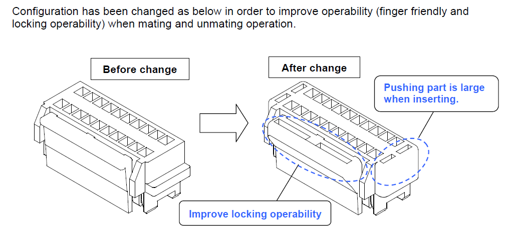
GHD Series
Modified in 2007, the (F) indicates the housing as a “finger friendly” style to improve handling during mating and unmating operations. Please refer to the following diagram:
Gold Plating
Certain connectors are offered with gold plating depending on the series and / or the JST part number. Most are custom per customer / request. For details please contact your sales representative at the following link: JST Reps and Distributors
The following table is our general gold plating nomenclature:
Gold Plating Table
| SYMBOL | GOLD PLATING THICKNESS | PLATING PLACEMENT | NICKEL UNDERPLATING | TIN PLATING | NOTES |
|---|---|---|---|---|---|
| G | Flash (over 0.06 μm / 2 μi) | Overall | 2~4 μm / 80~160μi | - | - |
| GA | Flash (over 0.06 μm / 2 μi) | Selective | 2~4 μm / 80~160μi | - | - |
| GAN | Flash (over 0.06 μm / 2 μi) | Selective | 2~4 μm / 80~160μi | - | Ni Stripe |
| GB | Flash (over 0.06 μm / 2 μi) | Selective | 2~4 μm / 80~160μi | 1-3μm / 40-120μi or 1.5~3.5 μm / 60~140 μi | - |
| GS | 0.1 μm / 4 μi | Overall | 2~4 μm / 80~160μi | - | - |
| GSAN | 0.1 μm / 4 μi | Selective | 2~4 μm / 80~160μi | - | Ni Stripe |
| GSA | 0.1 μm / 4 μi | Selective | 2~4 μm / 80~160μi | 1.5~3.5 μm / 60~140 μi | - |
| GC | 0.2 μm / 8 μi | Selective | 2~4 μm / 80~160μi | - | - |
| GD | 0.2 μm / 8 μi | Selective | 2~4 μm / 80~160μi | 1-3μm / 40-120μi | - |
| GE | 0.2 μm / 8 μi | Selective overall flash | 2~4 μm / 80~160μi | - | - |
| GW | 0.2 μm / 8 μi | Overall | 2~4 μm / 80~160μi | 1-3μm / 40-120μi | - |
| GWAN | 0.2 μm / 8 μi | Selective | 2~4 μm / 80~160μi | - | Ni Stripe |
| GC (Z) | 0.2 μm / 8 μi | Selective Barrel-flash | 2~4 μm / 80~160μi | - | - |
| GO.3 | 0.2 μm / 8 μi | Selective | Anti-electrolytic 0.1 μm / 4 μi | - | - |
| GAC | 0.3 μm / 12 μi | Overall | 2~4 μm / 80~160μi | - | - |
| GACN | 0.3 μm / 12 μi | Selective | 2~4 μm / 80~160μi | - | Ni Stripe |
| GR | 0.35μm / 14μi | Selective | 0.8μm / 30μi | 1-3μm / 40-120μi | - |
| GF | 0.4μm / 16μi | Selective | 2~4 μm / 80~160μi | - | - |
| GG | 0.4μm / 16μi | Selective | 2~4 μm / 80~160μi | 1-3μm / 40-120μi | - |
| GH | 0.4μm / 16μi | Selective overall flash | 2~4 μm / 80~160μi | - | - |
| GU | 0.4μm / 16μi | Overall | 2~4 μm / 80~160μi | - | - |
| GX | 0.5μm / 20μi | Overall | 2~4 μm / 80~160μi | - | - |
| GT | 0.6μm / 24μi | Overall | 2~4 μm / 80~160μi | - | - |
| GI | 0.76μm / 30μi | Selective | 2~4 μm / 80~160μi | - | - |
| GJ | 0.76μm / 30μi | Selective | 2~4 μm / 80~160μi | 1-3μm / 40-120μi or 1.5~3.5 μm / 60~140 μi | - |
| GK | 0.76μm / 30μi | Selective overall flash | 2~4 μm / 80~160μi | - | - |
| GP | 0.76μm / 30μi | Selective | 2.5μm / 98μi | - | - |
| GQ | 0.76μm / 30μi | Selective overall flash | 2.5μm / 98μi | - | - |
| GV | 0.76μm / 30μi | Overall | 2.5μm / 98μi | - | - |
| GZ | 0.76μm / 30μi | Overall | 1.3μm / 50μi | - | - |
| GL | 1.3μm / 50μi | Selective | 2~4 μm / 80~160μi | - | - |
| GM | 1.3μm / 50μi | Selective | 2~4 μm / 80~160μi | 1-3μm / 40-120μi | - |
| GN | 1.3μm / 50μi | Selective overall flash | 2~4 μm / 80~160μi | - | - |
| GY | 1.3μm / 50μi | Overall | 2~4 μm / 80~160μi | - | - |
| GAA | 1.3μm / 50μi | Overall | 2.5μm / 98μi | - | - |
| GAB | 1.3μm / 50μi | Selective overall flash | 2.5μm / 98μi | - | - |
JMC Series
The (S) indicates a modification made to the guide ribs of the receptacle to help prevent breakage during accidental, slantwise mating cycles instead of the proper straight mating method.
The (NSA) indicates a modification made to the guide ribs of the receptacle to help prevent breakage during accidental, slantwise mating cycles instead of the proper straight mating method as well as the inclusion of a Nickel stripe to help prevent solder from traveling up the contact during the reflow process.
JMD Series
The (S) indicates a modification made to the guide ribs of the receptacle to help prevent breakage during accidental, slantwise mating cycles instead of the proper straight mating method.
JU Series
The stacking height is 15.1mm (0.59″)
JWPF Series
JST does offer gold-plated versions. The part numbers are as follows:
SWPR-001GH-P025
SWPT-001GH-P025
The difference between SWPT-001T-P025 and SWPT-001T-025 is the base material. With the “P” it is a Phosphor Bronze material. Without the “P” it is a Brass material. The standard material is Phosphor Bronze.
KR Series / Family
The difference is the color; the “S” indicates white and the “H” indicates gray. From, fit and function they are otherwise the same and share the same termination tooling.
B( )B-PH-K-S is the standard, through-hole header in a natural white color. B( )B-PH-KL is a low insertion force type header in gray color.
NH Series
PAD Series
Example part numbers:
B10B-PADSS (LF)(SN)
B10B-PADSS-1 (LF)(SN)
Compared to…
B10B-PADSS-F (LF)(SN)
B10B-PADSS-1F (LF)(SN)
The difference is the raw material resin used. Without the “F”, it is glass-filled PBT. With the “F”, it is PA66.
PH Series
To order the top-entry, surface mount header of the PH series with removable suction cap (Kapton tape) for ease of pick-and-place vacuum nozzles, the part number would include an extra “T” after the packaging indicator.
For example:
Part number B2B-PH-SM4-TB (LF)(SN) does not include the suction cap.
Part number B2B-PH-SM4-TBT (LF)(SN) includes the suction cap.
JST cannot rework product you have already purchased without the suction cap.
Yes. There is a contact for the PH series that will work for 22AWG wire. The part number is SPH-001T-P0.5S. It has an AWG range of 26 to 22 with an insulation outer diameter range of 0.9 to 1.5mm. For 26 and 24 AWG, JST suggests using UL1007 wire. For 22AWG, we suggest UL1061 or UL1571.
B( )B-PH-K-S is the standard, through-hole header in a natural white color. B( )B-PH-KL is a low insertion force type header in gray color.
The difference is the insertion force. SPH-002T-P0.5S is the standard contact; SPH-002T-P0.5L is a low insertion force type contact.
These contacts do not share the same tooling.
The following are the recommended drill hole sizes for the most common PCB materials:
JST Part Numbers
B*B-PH-K-S (LF)(SN)
S*B-PH-K-S (LF)(SN)
Replace “*” with the applicable number of circuits (2 ~ 16).
Recommend PCB hole size (all dimensions are in mm):
Paper-based epoxy resin
Ø0.70 ~ 0.75 for 2 circuits
Ø0.75 ~ 0.80 for 3 ~ 16 circuits
Glass-based epoxy resin (without through-hole)
Ø0.70 ~ 0.75 for 2 circuits
Ø0.75 ~ 0.80 for 3 ~ 16 circuits
Note: Hole size of the paper-based epoxy PC board and glass-based epoxy resin PC board
(without through hole) is the value set for the drill hole (NC processing).
Glass-based epoxy resin (with through-hole)
Ø0.80 ~ 0.85 for 2 circuits
Ø0.85 ~ 0.90 for 3 ~ 16 circuits
Note: Hole size of glass-based epoxy PC board (with through-hole) is the finished dimension
after plating through-hole.
PHD Series
At this time, JST does not offer a wire-to-wire mate for the PHD series. It is deigned for wire-to-board applications only.
Replace ( ) with the applicable number of circuits.
The difference is the wafer material.
The suffixed “-B” on both the top and side-entry headers indicates the material is 66 Nylon.
Those without the “-B” suffix are glass-filled Nylon.
PND Series
The (T) indicates the packaging.
(T): Tray packaging
The PND series headers are packaged in trays to help prevent damage to the solder tails and housing during shipping and handling and for use in some automated PCB placement equipment.
Example part number: B30B-PNDZS-1 (T)(LF)(SN)
PNI Series
The difference between part number B**B-PNISK-1A(LF)(SN)(F) and the same without the (F) suffix is the wafer material. It is the part with the (F) that can only be purchased. It is the same glass-filled PA66, UL94V-0 material as called out on our data sheet online: http://www.jst-mfg.com/product/pdf/eng/ePNI.pdf
RCY Series
As an internal JST reference to control FIFO inventory, the (N) was applied to indicate a change in the quantity per reel from 7,500 pieces to 8,500 pieces.
The data sheets, product specifications and drawings will not indicate this internal reference though it is likely to be shown on the package labeling, packing lists and invoices to customers who purchase this item.
SH / SR Series
At this time, the SH series is only offered in its current configuration of wire-to-board. A wire-to-wire application option is not available.
JST does offer a flash gold-plated version of part number SSH-003T-P0.2-H. The part number is SSH-003GA-P0.2-H.
Contact with the “-H” suffix…

Contact without the “-H” suffix…

Part number SSH-003T-P0.2-H is a newer version and is called a “high-pressure contact type” compared to the older SSH-003T-P0.2. The contact point of the contact was modified for a more assured connection and to help prevent the contact from warping when mating with the header posts.
Both contacts share the same application crimp tooling for terminating to the applicable wire.
In the subject part numbers, replace the ( ) with the applicable number of circuits.
The difference is protrusions on the sides of the housings to make handling them easier. The SHR-( )V-S is without the protrusions and SHR-( )V-S-B is with the protrusions. Please see the image below for more details.

The complete data sheet can be down-loaded from the JST web site at the following link: SH Connector
The difference is the packaging. MINI-SSH-003T-P0.2 is packaged on a mini-reel of 1,000 pieces for use with the mini-reel hand tool WC-SH2832. Part number SSH-003T-P0.2 is packaged on the full size reel of 23,000 pieces MOQ for use on semi-auto bench presses.
SHD Series
Replace ( ) with the applicable number of circuits.
The “C” indicates the inclusion of a removable suction cap used for the ease of placement using pick and place equipment vacuum nozzles. Unlike Kapton tape applied to many of our SMT products, the “C” on this series is a hard plastic cap.
Shipping
SM Series
As an internal JST reference to control FIFO inventory, the (N) was applied to indicate a change in the quantity per reel from 7,500 pieces to 8,500 pieces.
The data sheets, product specifications and drawings will not indicate this internal reference though it is likely to be shown on the package labeling, packing lists and invoices to customers who purchase this item.
Strip Terminals and Chain Terminals
JST does not typically offer our strip terminals and chain terminals in loose piece (bulk) packaging. The reeled terminals are designed for large volume semi-automatic and fully-automatic wire termination equipment.
Hand tools are offered for loose contacts but most require the user to cut the terminal or contact off of the carrier strip before placing it into the hand tool for crimping.
Some of the JST authorized distributors do have the capabilities of removing the contacts from the carrier strip for those who wish to purchase loose contacts. Our network of authorized distributors can be found on our web site at the following URL:
The “P” indicates the base material. With the “P” the material is Phosphor Bronze. Without the “P” the material is Brass.
Suction Cap / Kapton Tape
For some of the connector series’, the top-entry surface mount headers require a suction cap for pick-n-place equipment vacuum nozzles. As such, those for which it applies would have an extra “T” suffix to the part number. For example, to have part number BM06B-SRSS-TB include the suction cap, it would be ordered as BM06B-SRSS-TBT. The same would apply to most top-entry headers with a “-TF” suffix. The SHD series is the exception whereas it uses a hard plastic cap thereby the suffix would be “-TFC”.
Tooling
Much of our tooling is available for lease. For details, please call our Service Engineering department at 800-947-1110.
No. The subject hand tool will not work with SPHD-002T-P0.5.
Tooling information can be found on our jst.com web site under Resources and Application Tooling Guide (Application Tooling Guide).
Choose the application of your terminal or connector (Crimp Style Connectors [these are crimp and poke types], Insulation Displacement Connectors [IDC / IDT type connectors, or Solderless Terminal & Splices [such as ring or spade lugs] then enter the exact part number or choose the part number from the scroll lists provided.
All the available tooling options and part numbers available will be shown.
USB Connectors
The following will explain the differences between the old and new, RoHS compliant USB Type A and Type B connectors:
Previous suffix of “-1”:
Housing resin material = PBT
Shell = Nickel-undercoated, tin / copper alloy plating
Contact solder tail = 100% tin-plating (reflow treated)
Now changed to new suffix of “-4D”:
Housing resin material = PBT
Shell = Nickel-undercoated, 100% pure tin-plating
Contact solder tail = 100% tin-plating (reflow treated)
************************************************
Previous suffix of “-2”:
Housing resin material = PPS
Shell = Nickel-undercoated, tin / copper alloy plating
Contact solder tail = 100% tin-plating (reflow treated)
Now changed to new suffix of “-4S”:
Housing resin material = PPS
Shell = Nickel-undercoated, 100% pure tin-plating
Contact solder tail = 100% tin-plating (reflow treated)
************************************************
Previous parts with a suffix of “-1NS” or without any designator have changed to “-4D” or “-4S” depending on the housing resin material.
VH Series
How do I order B3P-VH with the center post (pin #2) removed / omitted?
The part number would be B2P3-VH.
The RoHS compliant version adds (LF)(SN) to the part number suffix.
Does JST offer the VH headers with posts removed or omitted?
Yes, JST does offer the VH headers with posts omitted.
The difference is the material. With the “P it is a Phosphor Bronze material and is the standard to use. Without the “P” the material is Brass.
The strip length is 3.0mm to 3.5mm (0.118″ to 0.138″).
The strip length is 3.0mm to 3.5mm (0.118″ to 0.138″).
XA Series
Replace ** with the applicable number of positions / circuits.
JST does not offer the SMT top-entry XA headers with Kapton tape for straight pick-and-place equipment vacuum nozzles. JST suggests the PCB assembler to use a vacuum nozzle with a tip bent at 90° to pick the part out of the tape cavity by one of the side walls of this header.
Alternatively, if possible, mechanical pincers may also be used to extract the header from the tape cavity for placement onto the surface mount pads of the PCB.
The parts without the “N” incorporated in the part number may emit an unpleasant odor. In response to customer requests, the parts with the “N” use a raw material resin grade for the wafer material that incorporates countermeasures against the odor.
Without “N” part numbers in which an unpleasant odor may be present:
B( )B-XASK-1 (LF)(SN)
B( )B-XASK-1-A (LF)(SN)
With “N” part numbers that incorporate countermeasure against an odor:
B( )B-XASK-1N (LF)(SN)
B( )B-XASK-1N-A (LF)(SN)
Replace ( ) with the applicable number of circuits for the series.
(LF)(SN) is the RoHS compliant identifier.
Without “A” is without a locating / polarizing boss.
With “A” is with a locating / polarizing boss.
RE: BM*B-XASS-TF(LF)(SN)
The recommended storage temperature range is +5C to +35C. The recommended maximum storage humidity is 60%.
XH Series
In the part number, replace ( ) with the applicable number of circuits / positions.
The difference is the solder tail extension from the back edge of the header wall. Please refer to following diagram from the web site data sheet.

The difference is the base material.
SXH-001T-0.6 is made of Brass
SXH-001T-P0.6 is made of Phosphor Bronze (standard)
Phosphor Bronze contact retain their shape better than Brass contacts.
YL Series
Enacted in 1997, the (NN) indicates a slight modification made to the locking mechanism of the YLP housings as shown in the basic diagram below.
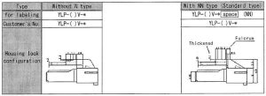
The (NN) will not be displayed on the data sheets or product specifications.
ZH / ZR Series
The ordering part number would be B**B-ZR-SM4-TFT (LF)(SN). Where “**” is replace with the applicable number of circuits.
What does the “-P” suffix indicate on part number ( )ZR-8M-P? [replace ( ) with the applicable number of circuits]
The “-P” indicates pre-tin plating and thus makes the IDC connector RoHS compliant.
The difference is the housing / wafer material…
SM3 is made of 46 Nylon glass-filled
SM4 is made of PA 6T Nylon glass-filled and is the RoHS compliant version.
The SM4 is better than SM3 for the higher temperatures required for the lead-free solder reflow process.
RE: B*B-ZR-SM4-*-TF(LF)(SN)
The recommended storage temperature range is +5C to +35C. The recommended maximum storage humidity is 60%.